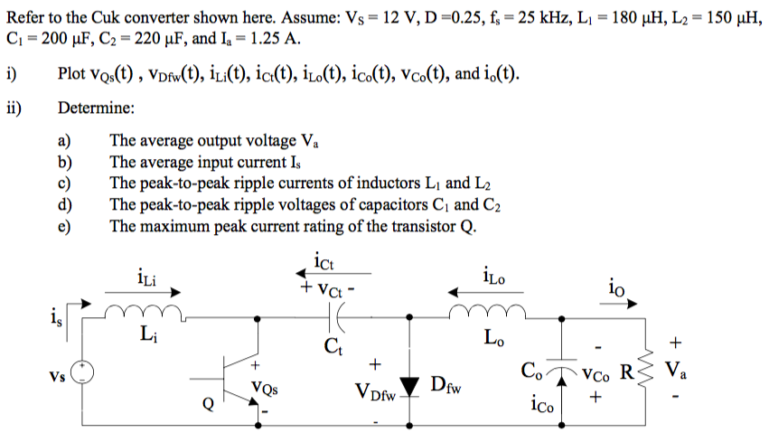

Solve for steady-state inductor currents and capacitor voltages The four equations obtained from volt-sec and charge balance: When ripple is neglected, iC2 is constant and equal to zero. Note: during both subintervals, the capacitor current iC2 is equal to the difference between the inductor current i2 and the load current V2/R. Waveforms: Inductor voltage vL1(t) vL1(t)Įquate average values to zero Inductor L2 voltage vL2(t)Įquate average values to zero Capacitor current iC2(t) waveform iC2(t) I2 – V2 / R (= 0) DTs Hence, to determine the steady-state conditions in the converter, let us sketch the inductor voltage and capacitor current waveforms, and equate their average values to zero. VL1 = Vg – V1 vL2 = – V2 i C1 = I 1 V i C2 = I 2 – 2 RĮquate average values to zero The principles of inductor volt-second and capacitor charge balance state that the average values of the periodic inductor voltage and capacitor current waveforms are zero, when the converter operates in steady state. Small ripple approximation for subinterval 2: Waveforms during subinterval 2 Diode conduction interval Inductor voltages and capacitor currents: vL1 = Vg – v1 vL2 = – v2 i C1 = i 1 v i C2 = i 2 – 2 R VL1 = Vg vL2 = – V1 – V2 i C1 = I 2 V i C2 = I 2 – 2 R Small ripple approximation for subinterval 1: VL1 = Vg vL2 = – v1 – v2 i C1 = i 2 v i C2 = i 2 – 2 R Waveforms during subinterval 1 MOSFET conduction interval Inductor voltages and capacitor currents: Switch in position 2: diode conducts Capacitor C1 is charged from input Switch in position 1: MOSFET conducts Capacitor C1 releases energy to output 29Ĭuk converter circuit with switch in positions 1 and 2 Solve the resulting four equations for the four unknowns I1, I2, V1, and V2.Simplify using the small ripple approximation.Apply charge balance to each capacitor current.Apply volt-second balance to each inductor voltage.I 1(t) = I 1 + i 1 -ripple(t) i 2(t) = I 2 + i 2 -ripple(t) v1(t) = V1 + v1 -ripple(t) v2(t) = V2 + v2 -ripple(t) To solve the converter in steady state, we want to find the dc components I1, I2, V1, and V2, when the ripples are small. Cuk converter: practical realization using MOSFET and diodeĬhapter 2: Principles of steady-state converter analysisĪnalysis strategy This converter has two inductor currents and two capacitor voltages, that can be expressed as


 0 kommentar(er)
